Hi Norman,
Step/Dir Pins are driven by hardware Step/Dir Generators assigned to fixed pins. The Axis Channel is configured to use a specific Step/Dir Generator Device through the OutputChan0 parameter. You must also know what type of drives you have and their input specifications to decide which mode will drive them.
See:
and
So for example to drive pins JP7 IO8 and IO9 in Open Collector Mode specify OutputChan0=0.
Limits and Home inputs are handled in software and may uses any spare input (those listed are just recommendations).
HTH Regards TK
| Group: DynoMotion |
Message: 12193 |
From: Norman Kwok |
Date: 9/2/2015 |
| Subject: Re: JP7 Sep & Direction for Axis X & Y |
Tom,
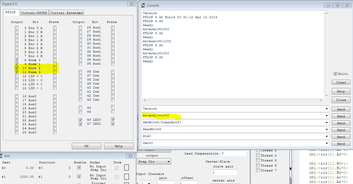
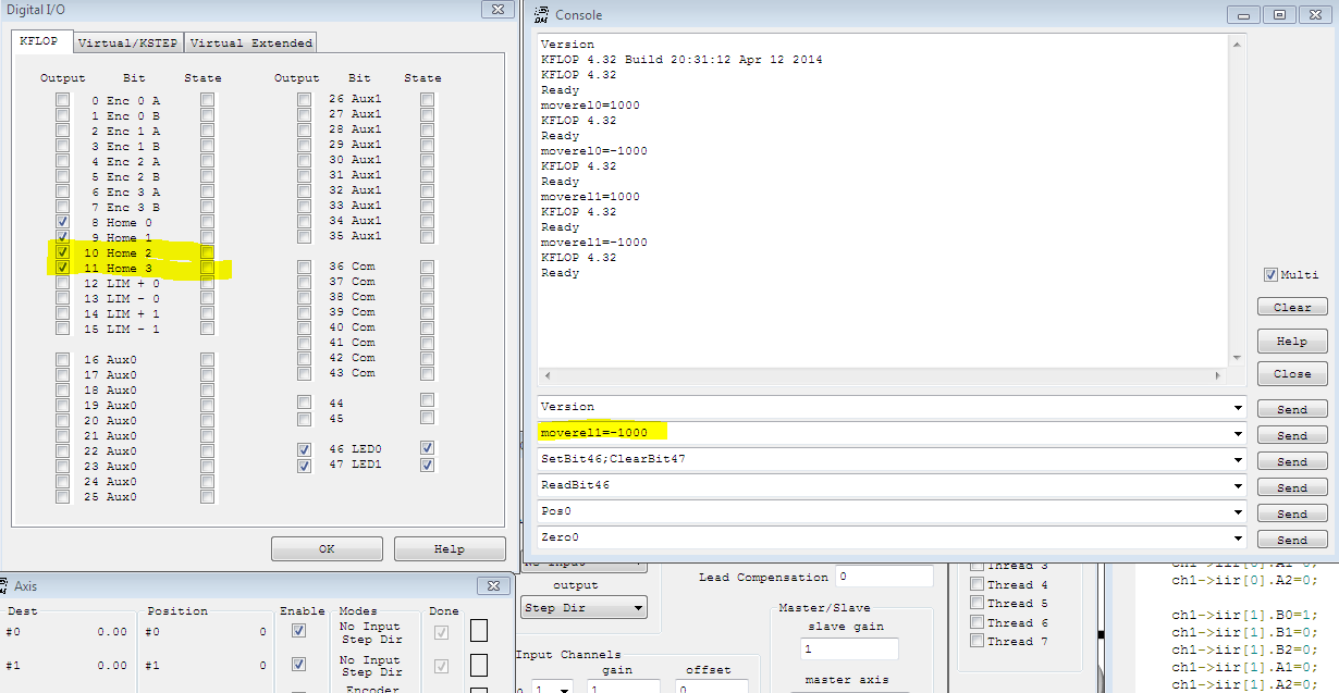
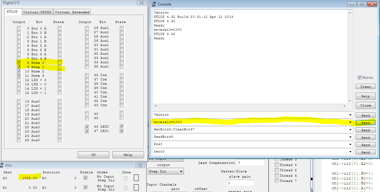
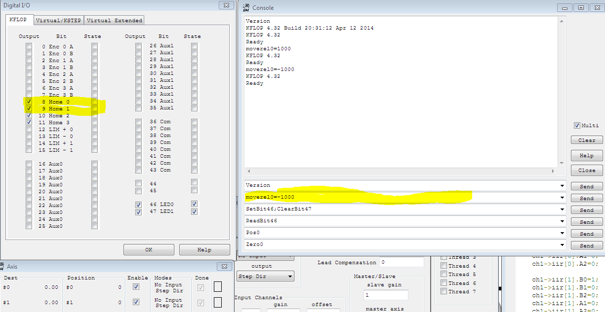
Thanks for those links which I have reviewed them before asking those questions. However, I don't see the direction signals being set when I moved both +/- direction. Here is the c-code for initial and please let me know if I am missing any setup parameter. Where do I specify which Output for those steps and directions? I am using IO8 for X Step, IO9 for X Direction, IO10 for Y Step and IO11 for Y Direction.
C Code: #include "KMotionDef.h"
main()
{
ch0->InputMode=NO_INPUT_MODE;
ch0->OutputMode=STEP_DIR_MODE;
ch0->Vel=40000;
ch0->Accel=400000;
ch0->Jerk=4e+006;
ch0->P=0;
ch0->I=0.01;
ch0->D=0;
ch0->FFAccel=0;
ch0->FFVel=0;
ch0->MaxI=200;
ch0->MaxErr=1e+006;
ch0->MaxOutput=200;
ch0->DeadBandGain=1;
ch0->DeadBandRange=0;
ch0->InputChan0=0;
ch0->InputChan1=0;
ch0->OutputChan0=0;
ch0->OutputChan1=0;
ch0->MasterAxis=-1;
ch0->LimitSwitchOptions=0x100;
ch0->LimitSwitchNegBit=0;
ch0->LimitSwitchPosBit=0;
ch0->SoftLimitPos=1e+009;
ch0->SoftLimitNeg=-1e+009;
ch0->InputGain0=1;
ch0->InputGain1=1;
ch0->InputOffset0=0;
ch0->InputOffset1=0;
ch0->OutputGain=1;
ch0->OutputOffset=0;
ch0->SlaveGain=1;
ch0->BacklashMode=BACKLASH_OFF;
ch0->BacklashAmount=0;
ch0->BacklashRate=0;
ch0->invDistPerCycle=1;
ch0->Lead=0;
ch0->MaxFollowingError=1000000000;
ch0->StepperAmplitude=20;
ch0->iir[0].B0=1;
ch0->iir[0].B1=0;
ch0->iir[0].B2=0;
ch0->iir[0].A1=0;
ch0->iir[0].A2=0;
ch0->iir[1].B0=1;
ch0->iir[1].B1=0;
ch0->iir[1].B2=0;
ch0->iir[1].A1=0;
ch0->iir[1].A2=0;
ch0->iir[2].B0=0.000768788;
ch0->iir[2].B1=0.00153758;
ch0->iir[2].B2=0.000768788;
ch0->iir[2].A1=1.92076;
ch0->iir[2].A2=-0.923833;
ch1->InputMode=NO_INPUT_MODE;
ch1->OutputMode=STEP_DIR_MODE;
ch1->Vel=40000;
ch1->Accel=8000;
ch1->Jerk=4e+006;
ch1->P=0;
ch1->I=0.01;
ch1->D=0;
ch1->FFAccel=0;
ch1->FFVel=0;
ch1->MaxI=200;
ch1->MaxErr=1e+006;
ch1->MaxOutput=200;
ch1->DeadBandGain=1;
ch1->DeadBandRange=0;
ch1->InputChan0=1;
ch1->InputChan1=0;
ch1->OutputChan0=1;
ch1->OutputChan1=0;
ch1->MasterAxis=-1;
ch1->LimitSwitchOptions=0x100;
ch1->LimitSwitchNegBit=0;
ch1->LimitSwitchPosBit=0;
ch1->SoftLimitPos=1e+009;
ch1->SoftLimitNeg=-1e+009;
ch1->InputGain0=1;
ch1->InputGain1=1;
ch1->InputOffset0=0;
ch1->InputOffset1=0;
ch1->OutputGain=1;
ch1->OutputOffset=0;
ch1->SlaveGain=1;
ch1->BacklashMode=BACKLASH_OFF;
ch1->BacklashAmount=0;
ch1->BacklashRate=0;
ch1->invDistPerCycle=1;
ch1->Lead=0;
ch1->MaxFollowingError=1000000000;
ch1->StepperAmplitude=20;
ch1->iir[0].B0=1;
ch1->iir[0].B1=0;
ch1->iir[0].B2=0;
ch1->iir[0].A1=0;
ch1->iir[0].A2=0;
ch1->iir[1].B0=1;
ch1->iir[1].B1=0;
ch1->iir[1].B2=0;
ch1->iir[1].A1=0;
ch1->iir[1].A2=0;
ch1->iir[2].B0=0.000769;
ch1->iir[2].B1=0.001538;
ch1->iir[2].B2=0.000769;
ch1->iir[2].A1=1.92081;
ch1->iir[2].A2=-0.923885;
EnableAxisDest(0,0);
EnableAxisDest(1,0);
DefineCoordSystem(0,1,-1,-1);
return 0;
}
Screen capture with XY Digital I/O.
Are you saying the IO8/9/10/11 are open collector and need to have pull-up resistors?
On Tuesday, September 1, 2015 4:31 PM, "Tom Kerekes tk@... [DynoMotion]" <DynoMotion@yahoogroups.com> wrote:
Hi Norman,
Step/Dir Pins are driven by hardware Step/Dir Generators assigned to fixed pins. The Axis Channel is configured to use a specific Step/Dir Generator Device through the OutputChan0 parameter. You must also know what type of drives you have and their input specifications to decide which mode will drive them.
See:
and
So for example to drive pins JP7 IO8 and IO9 in Open Collector Mode specify OutputChan0=0.
Limits and Home inputs are handled in software and may uses any spare input (those listed are just recommendations).
HTH Regards TK
| Group: DynoMotion |
Message: 12194 |
From: Tom Kerekes |
Date: 9/2/2015 |
| Subject: Re: JP7 Sep & Direction for Axis X & Y [4 Attachments] |
Hi Norman,
Because you have:
ch0->OutputChan0=0;
and
ch1->OutputChan0=1;
as described in the links you will be driving Step/Dir Generators 0 and 1 in Open collector mode which in turn will drive IOs 8,9,10,11. You will not see anything on those pins unless you have pull up resistors (or a load tied to +).
To have Step/Dir Generators 0 and 1 drive those same pins in LVTTL mode add 8 to the Output channel number. As:
ch0->OutputChan0=8;
and
ch1->OutputChan0=9;
You must explain what types if drives you have and include their input specifications in order for us to tell you how to wired and configure the Axes.
HTH Regards TK
| Group: DynoMotion |
Message: 12196 |
From: Norman Kwok |
Date: 9/2/2015 |
| Subject: Re: JP7 Sep & Direction for Axis X & Y |
Tom,
Thanks again for the explanation!
I missed the 8 offset in the OutputChanX and now I can see the I/O being toggle when moving the +/- direction.
As for the connection to the Stepper Driver, in my bench I have an old Vexta -Phase Driver UD2115A model. I have +5v with 500 ohms pull-up resistors tied to IO8 but the motor still is not moving. My connection:
I don't have any document for the Vexta Driver anymore. Are they connected correctly? Thanks!
Regards, Norman
On Wednesday, September 2, 2015 1:10 PM, "Tom Kerekes tk@... [DynoMotion]" <DynoMotion@yahoogroups.com> wrote:
Hi Norman,
Because you have:
ch0->OutputChan0=0;
and
ch1->OutputChan0=1;
as described in the links you will be driving Step/Dir Generators 0 and 1 in Open collector mode which in turn will drive IOs 8,9,10,11. You will not see anything on those pins unless you have pull up resistors (or a load tied to +).
To have Step/Dir Generators 0 and 1 drive those same pins in LVTTL mode add 8 to the Output channel number. As:
ch0->OutputChan0=8;
and
ch1->OutputChan0=9;
You must explain what types if drives you have and include their input specifications in order for us to tell you how to wired and configure the Axes.
HTH Regards TK
| Group: DynoMotion |
Message: 12197 |
From: Tom Kerekes |
Date: 9/2/2015 |
| Subject: Re: JP7 Sep & Direction for Axis X & Y [1 Attachment] |
Hi Norman,
500 ohms to +5V might not pull the input high enough (you might check with a volt meter).
Probably better to connect the + terminals directly to +5V. Then the connect the - terminals to the KFLOP Pins and use KFLOP Open Collector mode to sink to GND. That way the drive input will see the full 5V.
But without specs I'm guessing.
Regards TK
From: "Norman Kwok nkwok@... [DynoMotion]" <DynoMotion@yahoogroups.com>
To: "DynoMotion@yahoogroups.com" <DynoMotion@yahoogroups.com>
Sent: Wednesday, September 2, 2015 3:37 PM
Subject: Re: [DynoMotion] JP7 Sep & Direction for Axis X & Y [1 Attachment]
[Attachment(s) from Norman Kwok included below]
Tom,
Thanks again for the explanation!
I missed the 8 offset in the OutputChanX and now I can see the I/O being toggle when moving the +/- direction.
As for the connection to the Stepper Driver, in my bench I have an old Vexta -Phase Driver UD2115A model. I have +5v with 500 ohms pull-up resistors tied to IO8 but the motor still is not moving. My connection:
I don't have any document for the Vexta Driver anymore. Are they connected correctly? Thanks!
Regards, Norman
On Wednesday, September 2, 2015 1:10 PM, "Tom Kerekes tk@... [DynoMotion]" <DynoMotion@yahoogroups.com> wrote:
Hi Norman,
Because you have:
ch0->OutputChan0=0;
and
ch1->OutputChan0=1;
as described in the links you will be driving Step/Dir Generators 0 and 1 in Open collector mode which in turn will drive IOs 8,9,10,11. You will not see anything on those pins unless you have pull up resistors (or a load tied to +).
To have Step/Dir Generators 0 and 1 drive those same pins in LVTTL mode add 8 to the Output channel number. As:
ch0->OutputChan0=8;
and
ch1->OutputChan0=9;
You must explain what types if drives you have and include their input specifications in order for us to tell you how to wired and configure the Axes.
HTH Regards TK
| Group: DynoMotion |
Message: 12198 |
From: Norman Kwok |
Date: 9/3/2015 |
| Subject: Re: JP7 Sep & Direction for Axis X & Y |
Tom,
That did it, thanks for all the help and links!
Regards, Norman
On Wednesday, September 2, 2015 4:27 PM, "Tom Kerekes tk@... [DynoMotion]" <DynoMotion@yahoogroups.com> wrote:
Hi Norman,
500 ohms to +5V might not pull the input high enough (you might check with a volt meter).
Probably better to connect the + terminals directly to +5V. Then the connect the - terminals to the KFLOP Pins and use KFLOP Open Collector mode to sink to GND. That way the drive input will see the full 5V.
But without specs I'm guessing.
Regards TK
From: "Norman Kwok nkwok@... [DynoMotion]" <DynoMotion@yahoogroups.com>
To: "DynoMotion@yahoogroups.com" <DynoMotion@yahoogroups.com>
Sent: Wednesday, September 2, 2015 3:37 PM
Subject: Re: [DynoMotion] JP7 Sep & Direction for Axis X & Y [1 Attachment]
[Attachment(s) from Norman Kwok included below]
Tom,
Thanks again for the explanation!
I missed the 8 offset in the OutputChanX and now I can see the I/O being toggle when moving the +/- direction.
As for the connection to the Stepper Driver, in my bench I have an old Vexta -Phase Driver UD2115A model. I have +5v with 500 ohms pull-up resistors tied to IO8 but the motor still is not moving. My connection:
I don't have any document for the Vexta Driver anymore. Are they connected correctly? Thanks!
Regards, Norman
On Wednesday, September 2, 2015 1:10 PM, "Tom Kerekes tk@... [DynoMotion]" <DynoMotion@yahoogroups.com> wrote:
Hi Norman,
Because you have:
ch0->OutputChan0=0;
and
ch1->OutputChan0=1;
as described in the links you will be driving Step/Dir Generators 0 and 1 in Open collector mode which in turn will drive IOs 8,9,10,11. You will not see anything on those pins unless you have pull up resistors (or a load tied to +).
To have Step/Dir Generators 0 and 1 drive those same pins in LVTTL mode add 8 to the Output channel number. As:
ch0->OutputChan0=8;
and
ch1->OutputChan0=9;
You must explain what types if drives you have and include their input specifications in order for us to tell you how to wired and configure the Axes.
HTH Regards TK
| Group: DynoMotion |
Message: 12374 |
From: nkwok |
Date: 10/8/2015 |
| Subject: Re: JP7 Sep & Direction for Axis X & Y |
Tom,
I ran into different situation and see if you can help again!
I have wired per your recommendation and it was working until I used an external power supply to JR1 instead of the USB power (with J3 jumper removed). Once I am using an external power supply, the direction of motor (physical movement) did not change neither for X +/- nor Y +/- (always heading to one direction). I measured the voltage of the signal at the KFLOP and it did change state (like external 3.79V/0.65V, USB 3.7V/0.59V). I have attached the driver spec with the wiring diagram and see if you can see why.
The only different that I could see is that the +V is around 4.9V for USB, and around 5.25V for an external power supply.
Regards, Norman |
|
|
@@attachment@@
|
| Group: DynoMotion |
Message: 12375 |
From: Tom Kerekes |
Date: 10/9/2015 |
| Subject: Re: JP7 Sep & Direction for Axis X & Y [1 Attachment] |
Hi Norman,
What Step/Dir Output mode are you using? Open collector or LVTTL?
Regards TK
| Group: DynoMotion |
Message: 12376 |
From: Norman Kwok |
Date: 10/9/2015 |
| Subject: Re: JP7 Sep & Direction for Axis X & Y |
Tom,
I am using JP7 pin 8,9,10,11 for step/direction (that should be open-collector, right?). Here is the c-code for initial.
ch0->InputMode=NO_INPUT_MODE; ch0->OutputMode=STEP_DIR_MODE; ch0->Vel=40000; ch0->Accel=400000; ch0->Jerk=4e+006; ch0->P=0; ch0->I=0.01; ch0->D=0; ch0->FFAccel=0; ch0->FFVel=0; ch0->MaxI=200; ch0->MaxErr=1e+006; ch0->MaxOutput=200; ch0->DeadBandGain=1; ch0->DeadBandRange=0; ch0->InputChan0=0; ch0->InputChan1=0; ch0->OutputChan0=0; ch0->OutputChan1=0; ch0->MasterAxis=-1; ch0->LimitSwitchOptions=0x11f; ch0->LimitSwitchNegBit=1; ch0->LimitSwitchPosBit=0; ch0->SoftLimitPos=1e+009; ch0->SoftLimitNeg=-1e+009; ch0->InputGain0=1; ch0->InputGain1=1; ch0->InputOffset0=0; ch0->InputOffset1=0; ch0->OutputGain=1; ch0->OutputOffset=0; ch0->SlaveGain=1; ch0->BacklashMode=BACKLASH_OFF; ch0->BacklashAmount=0; ch0->BacklashRate=0; ch0->invDistPerCycle=1; ch0->Lead=0; ch0->MaxFollowingError=1000000000; ch0->StepperAmplitude=20;
ch0->iir[0].B0=1; ch0->iir[0].B1=0; ch0->iir[0].B2=0; ch0->iir[0].A1=0; ch0->iir[0].A2=0;
ch0->iir[1].B0=1; ch0->iir[1].B1=0; ch0->iir[1].B2=0; ch0->iir[1].A1=0; ch0->iir[1].A2=0;
ch0->iir[2].B0=0.000768788; ch0->iir[2].B1=0.00153758; ch0->iir[2].B2=0.000768788; ch0->iir[2].A1=1.92076; ch0->iir[2].A2=-0.923833;
ch1->InputMode=NO_INPUT_MODE; ch1->OutputMode=STEP_DIR_MODE; ch1->Vel=40000; ch1->Accel=8000; ch1->Jerk=4e+006; ch1->P=0; ch1->I=0.01; ch1->D=0; ch1->FFAccel=0; ch1->FFVel=0; ch1->MaxI=200; ch1->MaxErr=1e+006; ch1->MaxOutput=200; ch1->DeadBandGain=1; ch1->DeadBandRange=0; ch1->InputChan0=1; ch1->InputChan1=0; ch1->OutputChan0=1; ch1->OutputChan1=0; ch1->MasterAxis=-1; ch1->LimitSwitchOptions=0x11f; ch1->LimitSwitchNegBit=3; ch1->LimitSwitchPosBit=2; ch1->SoftLimitPos=1e+009; ch1->SoftLimitNeg=-1e+009; ch1->InputGain0=1; ch1->InputGain1=1; ch1->InputOffset0=0; ch1->InputOffset1=0; ch1->OutputGain=1; ch1->OutputOffset=0; ch1->SlaveGain=1; ch1->BacklashMode=BACKLASH_OFF; ch1->BacklashAmount=0; ch1->BacklashRate=0; ch1->invDistPerCycle=1; ch1->Lead=0; ch1->MaxFollowingError=1000000000; ch1->StepperAmplitude=20;
ch1->iir[0].B0=1; ch1->iir[0].B1=0; ch1->iir[0].B2=0; ch1->iir[0].A1=0; ch1->iir[0].A2=0;
ch1->iir[1].B0=1; ch1->iir[1].B1=0; ch1->iir[1].B2=0; ch1->iir[1].A1=0; ch1->iir[1].A2=0;
ch1->iir[2].B0=0.000769; ch1->iir[2].B1=0.001538; ch1->iir[2].B2=0.000769; ch1->iir[2].A1=1.92081; ch1->iir[2].A2=-0.923885;
EnableAxisDest(0,ch0->Dest); EnableAxisDest(1,ch1->Dest); DefineCoordSystem(0,1,-1,-1);
// Laser Status Bits
SetBitDirection(36, 1); SetBitDirection(37, 1); SetBitDirection(38, 1); SetBitDirection(39, 1); // Laser Test Status Bits SetBitDirection(40, 1); SetBitDirection(41, 1); SetBitDirection(42, 1); SetBitDirection(43, 1); // Setup Axis-X/Y Limit and Home SetBitDirection(0, 1); // X Limit+ SetBitDirection(1, 1); // X Limit-
SetBitDirection(2, 1); // Y Limit+ SetBitDirection(3, 1); // Y Limit-
Regards, Norman
On Friday, October 9, 2015 11:40 AM, "Tom Kerekes tk@... [DynoMotion]" <DynoMotion@yahoogroups.com> wrote:
Hi Norman,
What Step/Dir Output mode are you using? Open collector or LVTTL?
Regards TK
| Group: DynoMotion |
Message: 12377 |
From: Tom Kerekes |
Date: 10/9/2015 |
| Subject: Re: JP7 Sep & Direction for Axis X & Y |
Hi Norman,
Your Init program seems to be configuring bits as Outputs that are labeled as inputs and status. Is this correct? A direction of 1 is an Output. 0 would be an input. You might damage KFLOP if you configure the I/O as Output and then force drive it externally as an input.
// Laser Status Bits
SetBitDirection(36,
1);
SetBitDirection(37,
1);
SetBitDirection(38,
1);
SetBitDirection(39,
1);
//
Laser Test Status Bits
SetBitDirection(40,
1);
SetBitDirection(41,
1);
SetBitDirection(42,
1);
SetBitDirection(43,
1);
//
Setup Axis-X/Y Limit and Home
SetBitDirection(0,
1); //
X Limit+
SetBitDirection(1,
1); //
X Limit-
SetBitDirection(2,
1); //
Y Limit+
SetBitDirection(3,
1); //
Y Limit-
Regarding the +5.25 voltage: How did you finally end up wiring
these?
You do seem to be configuring as Open Collector Drive correctly.
The +5.25 voltage might be high enough that when the pin floats high
to ~3.79V then the input still "sees"
5.25 - 3.79 = 1.46V and the input opto doesn't turn off.
I don't see any spec on minimum voltage to turn on or maximum
voltage to turn off.
If this is the case you might try:
#1 - Connect the opto anodes to KFLOP +3.3V instead of the 5.25V
supply. The risk here is 3.3V - 0.59V = 2.71V is not enough to turn
on (although if 1.46V turns on then 2.71 certainly should turn on).
TTL mode might be a good choice in this case to actively drive the
pin low and high.
#2 - add a series diode (should drop the voltage by ~ 0.6V) 1.46 -
0.6 = 0.86V (should definitely turn off). The risk here is 5.25 -
0.6 - 0.65 = 4V is insufficient to turn on the opto (unlikely).
#3 - add a 5V Line driver such as (just use the + differential
output and ignore the - output) :
http://cnc4pc.com/product_info.php/differential-line-driver-p-337
HTH
Regards
TK
On 10/9/2015 11:59 AM, Norman Kwok
nkwok@... [DynoMotion] wrote:
Tom,
I am using JP7
pin 8,9,10,11 for step/direction (that should be
open-collector, right?). Here is the c-code for
initial.
ch0->InputMode=NO_INPUT_MODE;
ch0->OutputMode=STEP_DIR_MODE;
ch0->Vel=40000;
ch0->Accel=400000;
ch0->Jerk=4e+006;
ch0->P=0;
ch0->I=0.01;
ch0->D=0;
ch0->FFAccel=0;
ch0->FFVel=0;
ch0->MaxI=200;
ch0->MaxErr=1e+006;
ch0->MaxOutput=200;
ch0->DeadBandGain=1;
ch0->DeadBandRange=0;
ch0->InputChan0=0;
ch0->InputChan1=0;
ch0->OutputChan0=0;
ch0->OutputChan1=0;
ch0->MasterAxis=-1;
ch0->LimitSwitchOptions=0x11f;
ch0->LimitSwitchNegBit=1;
ch0->LimitSwitchPosBit=0;
ch0->SoftLimitPos=1e+009;
ch0->SoftLimitNeg=-1e+009;
ch0->InputGain0=1;
ch0->InputGain1=1;
ch0->InputOffset0=0;
ch0->InputOffset1=0;
ch0->OutputGain=1;
ch0->OutputOffset=0;
ch0->SlaveGain=1;
ch0->BacklashMode=BACKLASH_OFF;
ch0->BacklashAmount=0;
ch0->BacklashRate=0;
ch0->invDistPerCycle=1;
ch0->Lead=0;
ch0->MaxFollowingError=1000000000;
ch0->StepperAmplitude=20;
ch0->iir[0].B0=1;
ch0->iir[0].B1=0;
ch0->iir[0].B2=0;
ch0->iir[0].A1=0;
ch0->iir[0].A2=0;
ch0->iir[1].B0=1;
ch0->iir[1].B1=0;
ch0->iir[1].B2=0;
ch0->iir[1].A1=0;
ch0->iir[1].A2=0;
ch0->iir[2].B0=0.000768788;
ch0->iir[2].B1=0.00153758;
ch0->iir[2].B2=0.000768788;
ch0->iir[2].A1=1.92076;
ch0->iir[2].A2=-0.923833;
ch1->InputMode=NO_INPUT_MODE;
ch1->OutputMode=STEP_DIR_MODE;
ch1->Vel=40000;
ch1->Accel=8000;
ch1->Jerk=4e+006;
ch1->P=0;
ch1->I=0.01;
ch1->D=0;
ch1->FFAccel=0;
ch1->FFVel=0;
ch1->MaxI=200;
ch1->MaxErr=1e+006;
ch1->MaxOutput=200;
ch1->DeadBandGain=1;
ch1->DeadBandRange=0;
ch1->InputChan0=1;
ch1->InputChan1=0;
ch1->OutputChan0=1;
ch1->OutputChan1=0;
ch1->MasterAxis=-1;
ch1->LimitSwitchOptions=0x11f;
ch1->LimitSwitchNegBit=3;
ch1->LimitSwitchPosBit=2;
ch1->SoftLimitPos=1e+009;
ch1->SoftLimitNeg=-1e+009;
ch1->InputGain0=1;
ch1->InputGain1=1;
ch1->InputOffset0=0;
ch1->InputOffset1=0;
ch1->OutputGain=1;
ch1->OutputOffset=0;
ch1->SlaveGain=1;
ch1->BacklashMode=BACKLASH_OFF;
ch1->BacklashAmount=0;
ch1->BacklashRate=0;
ch1->invDistPerCycle=1;
ch1->Lead=0;
ch1->MaxFollowingError=1000000000;
ch1->StepperAmplitude=20;
ch1->iir[0].B0=1;
ch1->iir[0].B1=0;
ch1->iir[0].B2=0;
ch1->iir[0].A1=0;
ch1->iir[0].A2=0;
ch1->iir[1].B0=1;
ch1->iir[1].B1=0;
ch1->iir[1].B2=0;
ch1->iir[1].A1=0;
ch1->iir[1].A2=0;
ch1->iir[2].B0=0.000769;
ch1->iir[2].B1=0.001538;
ch1->iir[2].B2=0.000769;
ch1->iir[2].A1=1.92081;
ch1->iir[2].A2=-0.923885;
EnableAxisDest(0,ch0->Dest);
EnableAxisDest(1,ch1->Dest);
DefineCoordSystem(0,1,-1,-1);
//
Laser Status Bits
SetBitDirection(36,
1);
SetBitDirection(37,
1);
SetBitDirection(38,
1);
SetBitDirection(39,
1);
//
Laser Test Status Bits
SetBitDirection(40,
1);
SetBitDirection(41,
1);
SetBitDirection(42,
1);
SetBitDirection(43,
1);
//
Setup Axis-X/Y Limit and Home
SetBitDirection(0,
1); //
X Limit+
SetBitDirection(1,
1); //
X Limit-
SetBitDirection(2,
1); //
Y Limit+
SetBitDirection(3,
1); //
Y Limit-
Regards,
Norman
Hi Norman,
What
Step/Dir Output mode are you using?
Open collector or LVTTL?
Regards
TK
| Group: DynoMotion |
Message: 12379 |
From: nkwok |
Date: 10/11/2015 |
| Subject: Re: JP7 Sep & Direction for Axis X & Y |
Tom,
I was using for testing when I did not have the physical motor and limit switch. I clicked on them with KMotion Digital I/O for testing only. Thanks for pointing it out!
I ended up using the 3.3V instead of 5V and it is working, thanks!
Regards, Norman ---In DynoMotion@yahoogroups.com, <tk@...> wrote : Hi Norman,Your Init program seems to be configuring bits as Outputs that are labeled as inputs and status. Is this correct? A direction of 1 is an Output. 0 would be an input. You might damage KFLOP if you configure the I/O as Output and then force drive it externally as an input. // Laser Status Bits
SetBitDirection(36,
1); SetBitDirection(37,
1); SetBitDirection(38,
1); SetBitDirection(39,
1); //
Laser Test Status Bits SetBitDirection(40,
1); SetBitDirection(41,
1); SetBitDirection(42,
1); SetBitDirection(43,
1); //
Setup Axis-X/Y Limit and Home SetBitDirection(0,
1); //
X Limit+ SetBitDirection(1,
1); //
X Limit-
SetBitDirection(2,
1); //
Y Limit+ SetBitDirection(3,
1); //
Y Limit-
Regarding the +5.25 voltage: How did you finally end up wiring
these?
You do seem to be configuring as Open Collector Drive correctly.
The +5.25 voltage might be high enough that when the pin floats high
to ~3.79V then the input still "sees"
5.25 - 3.79 = 1.46V and the input opto doesn't turn off.
I don't see any spec on minimum voltage to turn on or maximum
voltage to turn off.
If this is the case you might try:
#1 - Connect the opto anodes to KFLOP +3.3V instead of the 5.25V
supply. The risk here is 3.3V - 0.59V = 2.71V is not enough to turn
on (although if 1.46V turns on then 2.71 certainly should turn on).
TTL mode might be a good choice in this case to actively drive the
pin low and high.
#2 - add a series diode (should drop the voltage by ~ 0.6V) 1.46 -
0.6 = 0.86V (should definitely turn off). The risk here is 5.25 -
0.6 - 0.65 = 4V is insufficient to turn on the opto (unlikely).
#3 - add a 5V Line driver such as (just use the + differential
output and ignore the - output) :
http://cnc4pc.com/product_info.php/differential-line-driver-p-337
HTH
Regards
TK
On 10/9/2015 11:59 AM, Norman Kwok
nkwok@... [DynoMotion] wrote: Tom,
I am using JP7
pin 8,9,10,11 for step/direction (that should be
open-collector, right?). Here is the c-code for
initial.
ch0->InputMode=NO_INPUT_MODE; ch0->OutputMode=STEP_DIR_MODE; ch0->Vel=40000; ch0->Accel=400000; ch0->Jerk=4e+006; ch0->P=0; ch0->I=0.01; ch0->D=0; ch0->FFAccel=0; ch0->FFVel=0; ch0->MaxI=200; ch0->MaxErr=1e+006; ch0->MaxOutput=200; ch0->DeadBandGain=1; ch0->DeadBandRange=0; ch0->InputChan0=0; ch0->InputChan1=0; ch0->OutputChan0=0; ch0->OutputChan1=0; ch0->MasterAxis=-1; ch0->LimitSwitchOptions=0x11f; ch0->LimitSwitchNegBit=1; ch0->LimitSwitchPosBit=0; ch0->SoftLimitPos=1e+009; ch0->SoftLimitNeg=-1e+009; ch0->InputGain0=1; ch0->InputGain1=1; ch0->InputOffset0=0; ch0->InputOffset1=0; ch0->OutputGain=1; ch0->OutputOffset=0; ch0->SlaveGain=1; ch0->BacklashMode=BACKLASH_OFF; ch0->BacklashAmount=0; ch0->BacklashRate=0; ch0->invDistPerCycle=1; ch0->Lead=0; ch0->MaxFollowingError=1000000000; ch0->StepperAmplitude=20;
ch0->iir[0].B0=1; ch0->iir[0].B1=0; ch0->iir[0].B2=0; ch0->iir[0].A1=0; ch0->iir[0].A2=0;
ch0->iir[1].B0=1; ch0->iir[1].B1=0; ch0->iir[1].B2=0; ch0->iir[1].A1=0; ch0->iir[1].A2=0;
ch0->iir[2].B0=0.000768788; ch0->iir[2].B1=0.00153758; ch0->iir[2].B2=0.000768788; ch0->iir[2].A1=1.92076; ch0->iir[2].A2=-0.923833;
ch1->InputMode=NO_INPUT_MODE; ch1->OutputMode=STEP_DIR_MODE; ch1->Vel=40000; ch1->Accel=8000; ch1->Jerk=4e+006; ch1->P=0; ch1->I=0.01; ch1->D=0; ch1->FFAccel=0; ch1->FFVel=0; ch1->MaxI=200; ch1->MaxErr=1e+006; ch1->MaxOutput=200; ch1->DeadBandGain=1; ch1->DeadBandRange=0; ch1->InputChan0=1; ch1->InputChan1=0; ch1->OutputChan0=1; ch1->OutputChan1=0; ch1->MasterAxis=-1; ch1->LimitSwitchOptions=0x11f; ch1->LimitSwitchNegBit=3; ch1->LimitSwitchPosBit=2; ch1->SoftLimitPos=1e+009; ch1->SoftLimitNeg=-1e+009; ch1->InputGain0=1; ch1->InputGain1=1; ch1->InputOffset0=0; ch1->InputOffset1=0; ch1->OutputGain=1; ch1->OutputOffset=0; ch1->SlaveGain=1; ch1->BacklashMode=BACKLASH_OFF; ch1->BacklashAmount=0; ch1->BacklashRate=0; ch1->invDistPerCycle=1; ch1->Lead=0; ch1->MaxFollowingError=1000000000; ch1->StepperAmplitude=20;
ch1->iir[0].B0=1; ch1->iir[0].B1=0; ch1->iir[0].B2=0; ch1->iir[0].A1=0; ch1->iir[0].A2=0;
ch1->iir[1].B0=1; ch1->iir[1].B1=0; ch1->iir[1].B2=0; ch1->iir[1].A1=0; ch1->iir[1].A2=0;
ch1->iir[2].B0=0.000769; ch1->iir[2].B1=0.001538; ch1->iir[2].B2=0.000769; ch1->iir[2].A1=1.92081; ch1->iir[2].A2=-0.923885;
EnableAxisDest(0,ch0->Dest); EnableAxisDest(1,ch1->Dest); DefineCoordSystem(0,1,-1,-1);
//
Laser Status Bits
SetBitDirection(36,
1); SetBitDirection(37,
1); SetBitDirection(38,
1); SetBitDirection(39,
1); //
Laser Test Status Bits SetBitDirection(40,
1); SetBitDirection(41,
1); SetBitDirection(42,
1); SetBitDirection(43,
1); //
Setup Axis-X/Y Limit and Home SetBitDirection(0,
1); //
X Limit+ SetBitDirection(1,
1); //
X Limit-
SetBitDirection(2,
1); //
Y Limit+ SetBitDirection(3,
1); //
Y Limit-
Regards, Norman
Hi Norman,
What
Step/Dir Output mode are you using?
Open collector or LVTTL?
Regards TK
| | | | | | | | | | | | | | | | | | | |
.png)